

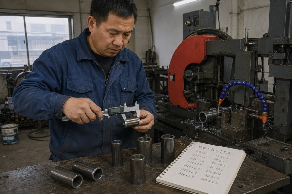
A pipe cutting machine can look perfect on paper and still ruin a customer’s fit-up. Our Wenzhou workshop learned this early, so now we verify precision before quoting anything.
To determine if a pipe cutting machine meets customer precision needs, first define the exact tolerance the finished part requires, collect the customer’s real material and processing conditions, then run trial cuts on that material and inspect length tolerance, repeatability, and cut squareness across a full batch.
That sounds simple. In practice, most buyers skip at least one of those steps. This article walks through each stage, so you can judge any machine with confidence before you sign a purchase order.
A procurement manager in the United States once asked me why two machines with identical brochures produced very different parts. The answer sits in how each supplier defines its tolerance numbers.
Expect a length tolerance of about ±0.05 mm to ±0.1 mm from servo-driven automatic pipe cutting machines, ±0.03 mm positioning accuracy from tube laser systems, around ±0.1 mm from general CNC cutters, and roughly 1 mm per 1000 mm from manual equipment.

The first thing I tell every buyer is this: clarify the precision indicators you truly need before you compare any machines. In our export work, we focus on three indicators. They are positioning accuracy 1, repeatability and accuracy over a batch, and finished-part dimensional tolerance. A brochure usually shows only the first one. Your welding line cares about the last one.
| Machine Type | Claimed Precision | Best Use Case |
|---|---|---|
| Servo-driven automatic saw | ±0.05 mm to ±0.1 mm length tolerance | High-volume length cutting |
| Tube laser system | ±0.03 mm to ±0.05 mm positioning; 0.02–0.05 mm repeatability | Complex profiles, tight fit-up |
| General CNC pipe cutter | Around ±0.1 mm | Standard production cutting |
| Manual cutting equipment | Around 1 mm per 1000 mm | Construction, rough fabrication |
Positioning accuracy tells you how well the axis moves. It does not tell you the squareness of cut, the surface roughness 2 of the edge, or how the number holds when wall thickness rises. Industrial tube lasers often hold ±0.1 to 0.3 mm on diameter in typical cases, and some reports show performance drifting once wall thickness passes 6 mm. So the claim "laser is always the most precise" is only half true. For simple length cuts on thick-walled pipe, a rigid saw with good servos can match the required tolerance at a much lower cost. Match the indicator to the end use, not to the marketing sheet.
We learned a hard lesson years ago when a demo cut on easy stock hid problems that only appeared on the customer's coated pipe. Now our team tests very differently.
Test accuracy by sending your actual pipe material to the supplier, requesting trial cut samples with unedited video of the full cycle, and demanding inspection reports for 50 to 100 consecutive parts. Then write those measured acceptance criteria directly into your purchase contract.

The core rule I follow is simple: never accept a showcase part. One perfect piece proves nothing about repeatability. When we run acceptance tests at our factory in Wenzhou, we design a precision test plan with the buyer before the machine is even built. Here is the five-step process we use.
| Indicator | Example Target | Measurement Tool |
|---|---|---|
| Length tolerance | ±0.1 mm | Calibrated caliper or CMM |
| Squareness of cut | ≤0.1 mm deviation | Square gauge |
| Surface roughness | Application-defined Ra value | Roughness tester |
| Batch repeatability | 100% of 50–100 parts in spec | Full inspection log |
Confirm one more thing before signing: whether the stated spec means positioning accuracy, repeatability, or finished cut dimensions. Suppliers often quote the most flattering number.
Every build forces a trade-off in our workshop: a stiffer frame and better servos raise cost, but skimping on either quietly destroys repeatability on long production runs.
Cutting precision depends on the CNC control system and servo motor resolution, frame rigidity and vibration damping, clamping design, blade or beam quality and kerf width control, plus compensation features for ovality, seam position, and thermal expansion during long production runs.

When buyers visit our production line, I always point them to six key components. Check these before you trust any tolerance claim, because each one can silently erode accuracy.
| Component | What to Check | How It Affects Precision |
|---|---|---|
| Machine frame and base | Structural rigidity, damping capacity | Vibration blurs the cut at high speed |
| CNC control system | Resolution, closed-loop feedback | Low resolution rounds off fine positioning |
| Servo motors | Servo motor resolution, encoder quality | Drives repeatability across thousands of cycles |
| Clamping mechanism | Grip force, jaw design | Over-clamping causes material deformation on thin walls |
| Cutting head or blade | Kerf width consistency, wear rate | A widening kerf shifts every dimension |
| Compensation systems | Ovality, seam, thermal sensors | Corrects real-world pipe imperfections |
Good software applies kerf compensation automatically and optimizes the path across complex multi-axis intersections. Better machines add a closed-loop feedback system with optical encoders 4, which detects mechanical play or beam drift during the cut and corrects it in real time. Some newer systems also use real-time thermal compensation sensors that adjust parameters as ambient temperature and material heat expansion change through a shift.
Real pipes are never perfect. Ovality, banana-shaped bow, and weld seams all shift the cut line. A machine that measures the pipe and compensates before cutting will hold tolerance where a basic machine fails. In my experience, this compensation capability separates a machine that passes a demo from one that survives two years of three-shift production.
One German distributor once sent us a tolerance sheet our standard model could not hold. Instead of overselling, our engineers redesigned the clamping and feed system around his spec.
Yes. Reputable suppliers can customize a pipe cutting machine to exact precision requirements through OEM/ODM development, upgrading servo motors, clamping fixtures, control software, and measurement systems, then validating the build with trial cuts and batch inspection data before shipment.

Customization is where our small Wenzhou team spends most of its engineering hours. We build non-standard metal processing machines for buyers in the United States, Germany, Japan, and beyond, and almost every project starts the same way. The buyer sends drawings, material samples, and a target dimensional tolerance. We respond with a design proposal, not a price list.
The final step matters most. Acceptance criteria, inspection method, and tolerance limits should all be written into the purchase agreement. A supplier who resists that clause is telling you something important.
Brochure numbers alone will burn you. Define the real tolerance, test on real material, inspect a full batch, and lock the criteria into your contract before buying.
Interested in sourcing the products mentioned in this article? See details and request a quote here:
1. NIST is the authoritative source for measurement science and positioning accuracy standards. ↩︎
2. ASME establishes technical standards for measuring surface texture and mechanical tolerances. ↩︎
3. ISO provides international standards for quality management and machine tool calibration. ↩︎
4. IEEE develops standards for electronic components and feedback systems used in industrial machinery. ↩︎
