

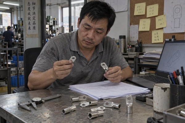
Many buyers email us one lug photo and ask for a price. That cable lug making machine quote then stalls for weeks. Clear customization requirements fix this before engineering starts.
To communicate customization requirements to cable lug making machine suppliers, send a structured technical brief: product drawings and samples, material grade, full size range, target good-parts output, required operations, applicable standards, factory utilities, and written acceptance-test criteria. Then confirm feasibility against the machine’s processing range and fixture limits.
Customization is not a request to “modify the machine.” It is a requirements exercise. The better you define the result, the less your supplier has to guess. Below, I walk through the four conversations that matter most, in the order we actually hold them with our own customers.
Last year a distributor sent us a crisp photo of a ring lug and nothing else. Our engineers could not even tell the barrel wall thickness from it.
Include 2D PDF and native CAD drawings, physical samples of each lug family, overall length and width, barrel diameter and wall thickness, palm shape, hole diameter and position, tolerances, surface finish or plating, discharge orientation, and a product matrix listing every model with its monthly volume.

A supplier designs around two things: the incoming material and the finished part. The machine sits in between. So the first document I ask for is never a machine wish list. It is a complete description of what you want to come out of the discharge chute.
A nominal cable size is not enough. Two lugs rated for the same 70 mm² conductor can have different barrel lengths, palm widths, wall thicknesses, and hole centers. Each of those differences changes the custom die sets, the feeder, and the stroke. The table below lists what our engineering team needs before we can draw a tooling concept.
| Drawing detail | Why the supplier needs it |
|---|---|
| Overall length and width | Sets feeder stroke, cut length, and discharge spacing |
| Barrel outer diameter and wall thickness | Determines forming force and tube feeder type |
| Palm shape and thickness | Defines flattening die and press tonnage |
| Hole diameter, count, and center position | Drives punch design and position tolerance |
| Inspection hole, chamfers, radii, embossing | Adds or removes a station in the cycle |
| Plating, finish, and color | Affects marking risk and handling surfaces |
| Dimensional tolerance 1s | Decides whether standard or precision tooling is required |
| Discharge orientation | Shapes the chute and any downstream counting |
Drawings describe one part. A product matrix describes your real operating range. List every lug model, its key dimensions, its material, its tooling requirement 2, and its expected monthly volume. Add a line for the full conductor range you plan to cover. In the market, ranges from 6 mm² up to 630 mm² appear in buyer requests, but no single feeder and die set covers that whole span well. Your matrix tells the supplier where the machine must be fast and where it only needs to be capable.
Attach a short bill of materials too. If some lugs arrive as pre-cut blanks and others as continuous tube, say so. If a future size is likely, mark it as "planned." We would rather leave room in the fixture now than redesign later.
Every project forces one choice on us: integrate every operation into one line, or split it across machines. Your process description decides which route is realistic.
Explain production process requirements with a step-by-step process map: list each operation from tube or strip feeding through cutting, flattening, punching, forming, deburring, inspection, and discharge. State which steps must be automatic, how many operators you allow, and how often you change sizes per shift.

Our own method is simple, and it is how I suggest you approach any supplier. We hold an early solution discussion to pin down the requirements first. Only after that do we confirm feasibility. We check feasibility against two hard limits: the machine's processing range and the fixture dimension limits. If your largest lug falls outside what the clamp can hold, or your smallest tube falls below what the feeder can grip, no amount of PLC programming will save the project. We say that early, and we expect a serious supplier to say it to you too.
Here is the sequence I recommend:
Not every requested change costs the same. Some are configuration choices. Some are real engineering. I ask customers to request a classification for each item, because it directly affects price, lead time, and after-sales technical support.
| Classification | Typical examples | Impact on project |
|---|---|---|
| Standard | Flattening, punching, cutting, basic discharge chute | Included in base machine |
| Configurable | Voltage and phase, PLC and HMI brand, feeder type, guarding, counting, color | Priced as options, short lead time |
| Newly engineered | New forming process, unusual hole patterns, orbital cutting for swarf-less edges, double-sided countersinking, automated terminal crimping, robotic loading | Separate design phase, longer delivery, tooling approval milestones |
Watch out for machines with similar names and different coverage. One "automatic lug machine" may combine tube feeding, flattening, punching, cutting, forming, and discharge in a single continuous cycle. Another with the same label may only punch and cut, leaving forming to a second press. For high-volume cold pressing technology, a dedicated line often wins. For varied, lower-volume work, a semi-automatic unit with manual loading and automatic forming may be the smarter choice. Say which world you live in.
A procurement manager in the US once asked me why our 380 V machine could not run on his 220 V shop line. The spec sheet had never mentioned utilities.
The specifications that matter most are material grade and wall thickness, full conductor and tube size range, good-parts output per hour, number and type of die sets, press tonnage, automation level, inspection and data functions, and factory utilities such as voltage, phase, and compressed-air pressure.

A good technical specifications sheet is not a copy of the supplier's brochure. It is your statement of needs, written so an engineer can act on it. The table below is the structure we use when we quote OEM/ODM manufacturing services for lug equipment. Each row answers a question an engineer will ask anyway.
| Specification area | What you should state | Published reference points to compare against |
|---|---|---|
| Material grade specifications | Copper or aluminium, grade and conductivity, temper, plating, tube OD and ID, wall thickness, incoming tolerance | Aluminium and thin-wall plated tube need different forming conditions than bare copper |
| Wire gauge compatibility | Minimum and maximum conductor cross-section, plus barrel diameter range | Some machine configurations list mould sizes from 10 to 300 mm², with separate feeder types for small and large sizes |
| Production capacity requirements | Required good pieces per hour, shifts per day, product mix, scrap allowance | Published machines quote roughly 13 to 19 pieces per minute; treat these as cycle rates, not guaranteed good output |
| Press and tooling | Tonnage, number of custom die sets included, die material and life, change method, spare die pricing | 30-ton hydraulic cylinders appear on several forming and punching machines |
| Utilities | Voltage, frequency, phase, connected load, air pressure and flow, hydraulic oil, footprint | Examples include three-phase 380 V with compressed air of at least 0.5 MPa; others offer 220 V 50 Hz as a configurable option |
| Inspection and data | Vision checks, hole gauging, reject separation, counting, exportable production data | Some suppliers quote a pass rate of at least 98%; ask how it was measured |
Many buyers now ask for servo-driven feeding and punching instead of hydraulics. Servo systems can lower energy use and improve stroke precision. But I do not accept that as a blanket rule. For heavy forming on thick-wall copper, a hydraulic press still delivers force cheaply and reliably. The right answer depends on your wall thickness and your tonnage. Put the trade-off in the discussion rather than specifying one technology by habit.
The same logic applies to Industry 4.0 requests. Real-time OEE tracking, remote diagnostics, smart tooling with wear sensors, and digital twin simulations 3 all have value. They also add cost and integration time. I suggest you list them, then ask the supplier to classify each as standard, configurable, or newly engineered. That way the quotation stays honest.
Finally, demand a quotation format that separates base machine, product-specific tooling, spare tooling, feeders, inspection, guarding, installation, training, freight, and warranty. A low headline price often hides excluded moulds or excluded commissioning. Ask who owns the tooling drawings and the PLC program backup. Ask for the remote support response time. These are specifications too.
We learned the hard way that a short demo with one easy size proves very little. Now every machine we ship runs a documented acceptance test first.
Turn expectations into measurable criteria: name the applicable standards, define dimensional and hole-position tolerances, burr limits, minimum sustained output, maximum reject rate, and changeover time. Then write these into a Factory Acceptance Test using your approved material and full product mix, with sample parts and data as proof.

Tell your supplier where the lugs will be sold. The market decides the standard, and the standard decides the measurable limits. Common references include:
These are not interchangeable. State the exact edition and product category. Then convert the standard into manufacturing numbers: dimensional tolerance, hole-position tolerance, burr height, forming accuracy, surface defects, and repeatability across a run. A supplier can only build to numbers.
Here is the pushback I hear most: "If the machine is built to the standard, my product is compliant." I disagree, and I say so to our own customers. A machine can be capable of producing compliant parts. Compliance of the finished lug still depends on your material, your tooling, your settings, and your process control 4 working together. You remain responsible for validating the product. The supplier is responsible for proving the machine's capability under agreed conditions. Keep those two responsibilities separate in the contract.
| Factory Acceptance Test item | What to agree in writing |
|---|---|
| Material and tooling | Buyer-approved raw material and approved die sets, not supplier demo stock |
| Product coverage | Representative sizes across the whole matrix, including the hardest one |
| Duration and quantity | Defined run time and sample count, not a two-minute demonstration |
| Output | Minimum sustained good parts per hour, measured after changeover |
| Quality limits | Maximum reject rate, dimensional capability, hole-position accuracy, surface quality |
| Changeover | Documented changeover time and repeatability after the change |
| Safety and controls | Guarding, interlocks, alarm behaviour, and recipe management |
| Data | Good-versus-reject counts, timestamped pressure and stroke data, fault history, exportable records |
Ask for sample parts, inspection results, and the full list of machine settings from the test. Claims such as ±0.05 mm repeatability or ±0.1 mm feed accuracy should be verified by these records, not by a brochure. Then schedule a site acceptance test after installation. Good after-sales technical support starts with a machine that already proved itself on your material.
Vague requests produce vague quotes and risky machines. Send a product dossier, process map, output target, standards list, utility schedule, and acceptance plan. Then your supplier stops guessing.
Interested in sourcing the products mentioned in this article? See details and request a quote here:
1. Engineering tolerance is the permissible limit of variation in a physical dimension. ↩︎
2. ISO standards define requirements for technical documentation and tooling in manufacturing. ↩︎
3. Digital twins are virtual representations used to simulate and optimize manufacturing processes. ↩︎
4. The IEC develops international standards for industrial-process measurement and control. ↩︎
