

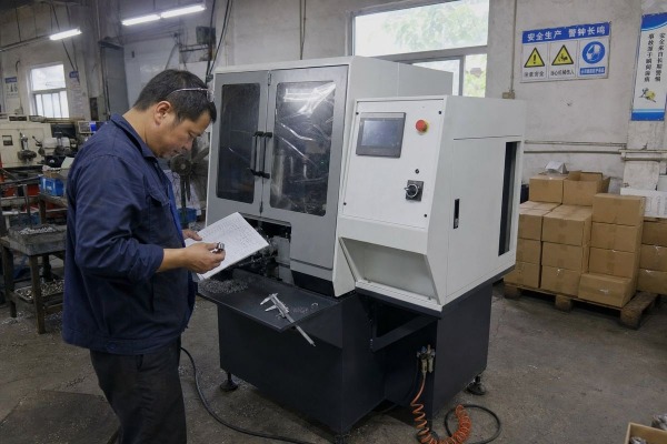
Choosing a fully automatic chamfering machine on spec sheets alone is risky PLC or CNC control system 1. On our Wenzhou production floor, I have seen buyers regret skipping the numbers that actually matter.
When buying a fully automatic chamfering machine, verify five core specs first: workpiece outer diameter range, processing length range, motor power, dimensional tolerance, and input air pressure. Then confirm cycle time, control system type, material compatibility, tooling changeover speed, and total machine footprint.
The problem is that most catalogs hide weaknesses behind big headline numbers. A machine may look fast but fail your tolerance. It may fit your diameter but not your length. Below, I break down each spec group so you can compare machines the way our engineers do.
A buyer from Mexico once sent us scrapped parts from his old chamfering machine. The chamfers drifted 0.3 mm across one shift. That single photo taught him why tolerance specs come first.
Verify the stated length tolerance and chamfer tolerance, typically ±0.05 mm on precision-class machines and ±0.1 mm on standard models. Also confirm repeatability across a full production run, how the tolerance is measured, and whether clamping rigidity holds that accuracy at rated speed.

Accuracy and repeatability 2 are not the same thing, and this distinction matters more than most spec sheets admit. Accuracy tells you how close a single chamfer is to the target dimension. Repeatability tells you whether part number 5,000 looks like part number 1. In our own quality checks, we run sample batches for customers before shipment and measure both. A machine with high speed but weak repeatability creates hidden costs. You pay for scrap, for secondary finishing, and for the inspection labor needed to catch bad parts.
Ask the supplier for these numbers, and ask how each one was tested:
| Spec | Typical Precision Class | Typical Standard Class | Why It Matters |
|---|---|---|---|
| Length tolerance | ±0.05 mm | ±0.1 mm | Controls final part dimension |
| Chamfer angle consistency | Programmable, stable | Fixed, may drift | Affects assembly fit |
| Chamfer depth control | Servo-controlled | Mechanical stop | Determines edge uniformity |
| Repeatability | Stated over 1,000+ cycles | Often unstated | Predicts scrap rate |
Tolerance claims are only valid if the clamping system and spindle stay rigid under cutting load. Precision machining 3 depends on the whole force path: clamp, workpiece, cutter, and frame. When we build machines for stainless steel parts, we reinforce the clamping fixture specifically, because harder materials push back harder. Ask whether the published tolerance was measured on aluminum or on the material you actually run. The difference can be significant.
Motor power is one of the five specs I always list first when quoting a machine, alongside diameter range, length range, tolerance, and air supply. There is a reason for that order.
Match motor power to your material and part size: compact machines run around 0.55–1.5 kW for small brass or aluminum parts, while steel tube lines need 3–5.5 kW or more. Then check spindle speed, typically 1,400–6,000 rpm, against your target cycle time.

Motor power determines what the machine can cut, and spindle speed determines how the cut finishes. But raw kilowatts alone do not tell the full story. Torque at cutting speed matters more than peak rpm, especially for thick-wall tube or alloy steel. When our team specifies a machine for stainless steel, we deliberately choose a larger motor than the aluminum equivalent, because stainless work-hardens and punishes underpowered spindles with tool wear and chatter.
| Machine Class | Motor Power | Typical Spindle Speed | Best For |
|---|---|---|---|
| Compact | 0.55–1.1 kW | 3,000–6,000 rpm | Small pins, fittings, Ø3–22 mm |
| Mid-range | 1.5–3 kW | 1,400–4,000 rpm | General steel and copper parts |
| Heavy-duty | 4–5.5 kW+ | 1,400–3,000 rpm | Thick-wall tube, Ø12–120 mm, long bars |
Published cycle claims range from about 2.5 seconds per operation to 30–40 pieces per minute on small-part machines. Here is the trap: spindle speed is rarely the bottleneck. The full cycle includes loading, clamping, cutting, chip removal, and unloading. Cycle time optimization means shortening the whole loop, not just the cut. When you calculate production volume requirements, work backward from pieces per hour needed, then ask the supplier to demonstrate a full loaded cycle on video. We record these demonstrations for every customer before shipment, and the numbers sometimes surprise even us.
Also weigh dual-head models. They chamfer both ends in one cycle, roughly halving handling time for symmetric parts.
Every quotation our engineering team prepares starts with two questions: what is the exact outer diameter range, and what is the processing length range? Everything else follows from those answers.
Confirm the machine covers your full minimum and maximum outer diameter and workpiece length, not just typical parts. Then verify material compatibility for your specific metals — mild steel, stainless, aluminum, copper, or brass — since each affects tooling, torque, and chip control differently.

Processing capacity is where most mismatches happen, and they are the most expensive mistakes to fix. Published diameter ranges vary enormously, from roughly Ø3–22 mm on compact units to Ø12–120 mm on larger chamfering lines. Work length ranges vary even more, from 25–150 mm on one model to 250–6,000 mm on long-bar systems. A machine that fits your diameter perfectly can still reject your parts because the length falls outside its feeding system.
Material affects tool wear, required spindle torque, chip formation, and surface finish. Aluminum cuts fast but produces stringy chips that can jam feeders. Stainless needs slower feeds and rigid clamping. Brass is forgiving but demands sharp tooling for clean edges. When a customer from India sent us drawings for mixed copper and steel terminals, we specified separate tooling sets and adjusted feed parameters for each, because one setup cannot optimally serve both. Send your actual part drawings to any supplier before committing. We test sample parts on our machines and return measured results, and I recommend you require the same from anyone you buy from.
A hard lesson from an early export project: two machines can both be labeled fully automatic, yet one still needs an operator standing beside it all day. The control architecture explains the difference.
Prioritize a PLC or CNC control system with an HMI touchscreen, stored part recipes, servo or pneumatic auto-clamping, and integrated auto-feeding and auto-ejection. Confirm input air supply of 0.6–0.8 MPa and correct voltage, since utilities directly limit clamping force and reliability.

The phrase fully automatic hides a wide spectrum. Real automation means the machine auto-feeds, auto-clamps, auto-cuts, auto-ejects, and ideally auto-adjusts. Anything less means labor cost stays in your process. Modern control systems built around PLC or CNC platforms let you store recipes for multiple part numbers, which matters enormously if you run mixed production. On the machines we build with touchscreen HMI panels, changing between saved part programs takes seconds, and features like chamfer angle adjustment and chamfer depth control become programmable values instead of mechanical adjustments.
| Feature | Basic Automatic | Fully Automatic (Recommended) |
|---|---|---|
| Feeding | Hand loading or chute | Vibratory bowl, linear feeder, or robotic loading |
| Clamping | Manual or simple pneumatic | Servo-assisted or hydraulic auto-clamp |
| Control | Relay or basic switches | PLC/CNC with HMI and stored recipes |
| Ejection | Manual removal | Auto-eject with chip collection chute |
| Changeover | 15–30 minutes | Quick-change tooling, under a few minutes |
Input air supply is on my personal top-five checklist for a reason. Most pneumatic clamping systems need 0.6–0.8 MPa. If your shop compressor cannot hold that pressure, clamping force drops, parts slip, and tolerance collapses. Check electrical supply too: machines ship configured for 220–240V, 380V, or 400V at different phases. We always confirm the destination country's power standard before wiring a machine for export, because rewiring on-site delays commissioning by days.
Finally, weigh tooling flexibility and material handling systems together. Quick-change tooling shortens setup between part sizes. Some models claim 45-second changeovers. For job shops, that single spec can matter more than raw speed. Some buyers argue for maximum automation to drive ROI through unattended operation; others prefer simpler machines with fewer servos and easier maintenance. My honest answer: the right machine is the one whose automation level matches your labor cost, part mix, and maintenance capability, not the one with the longest feature list.
Buying blind on headline specs invites scrap, downtime, and regret. Start with diameter range, length range, motor power, tolerance, and air supply — then verify everything with real sample parts.
1. Explains the functions and benefits of modern industrial control systems like PLC and CNC. ↩︎
2. Clarifies the difference between accuracy and repeatability in measurement and manufacturing. ↩︎
3. Provides a clear definition, processes, and applications of precision machining. ↩︎
