

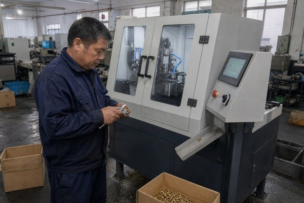
Choosing the wrong chamfer radius range on a fully automatic chamfering machine can quietly ruin a production line. I have seen it happen on our own shop floor in Wenzhou. A buyer picks a machine based on price, discovers the radius envelope does not match the part family, and then every changeover becomes a fight. Tooling costs pile up. Scrap rates climb. The good news is that the right range is not a mystery. It mostly comes down to your part dimensions, and there are clear benchmarks you can follow.
A fully automatic chamfering machine should support a chamfer radius range of roughly R0.5 mm to R5 mm, with R0.5–R3 mm as the practical standard band. R2.5 mm is the most common industrial benchmark, and the exact range needed depends mainly on your part or terminal size.
That is the short answer. But your parts, materials, and tolerances all shift the requirement. Let me walk you through how we help buyers pin down the exact range they actually need.
Last year, a customer sent us drawings for copper cable terminals 1 and asked for a single fixed radius. After reviewing the full part family, we quoted a range instead. Here is why.
Your required chamfer radius range depends primarily on your part or terminal size. For most terminal and small-part work, R0.5 mm to R5 mm covers nearly all real production needs, with R0.5–R3 mm handling standard jobs and larger radii reserved for heavier components.

In our experience building cable lug and terminal manufacturing equipment, the deciding factor is almost always the size of the workpiece. Our engineers have found that terminal work generally sits in the 0.5–5 mm band. Small brass terminals need light edge breaking around R0.5–R1 mm. Mid-size copper lugs typically call for R1.5–R2.5 mm 2. Heavy-gauge lugs and thicker bar stock push toward R3–R5 mm.
Do not specify a machine around a single drawing. Specify it around your whole part family. If your smallest part needs R0.5 mm and your largest needs R4 mm, your machine must cover that full envelope, either through programmable geometry or interchangeable cutting tools.
| Application | Typical Radius Range | Notes |
|---|---|---|
| Light deburring / edge breaking | R0.2–R0.5 mm | Removes sharp burrs only |
| Small terminals and pins | R0.5–R1.5 mm | Assembly lead-in, safety |
| Standard cable lugs | R1.5–R2.5 mm | R2.5 mm is the industry benchmark |
| Heavy lugs, bar and tube ends | R3–R5 mm | Tube chamfering, thicker stock |
| Weld preparation bevels 3 | Angle-based, not radius | Governed by chamfer angle and depth |
One more point. Many suppliers publish chamfer depth or chamfer angle instead of radius. So when you compare quotes, ask the vendor to translate their spec into radius terms. We do this for every customer drawing we receive, and it prevents costly misunderstandings.
There is a real trade-off we weigh in every design review: a wider radius envelope adds flexibility, but it also stresses the spindle, tooling, and fixturing in different ways.
A wider chamfer radius range increases machine versatility but demands stiffer construction, better tooling, and tighter control systems to hold precision. Machines optimized for a focused band, such as R0.5–R3 mm, typically achieve accuracy within ±0.05 mm more consistently than overly broad designs.

When we calibrate our machines before shipment, we test across the full advertised radius range, not just the middle. Here is why that matters. Cutting a large radius removes more material per pass. That raises cutting forces. Higher forces cause deflection in the spindle and fixture. Deflection destroys precision. So a machine that claims R0.5–R10 mm on a light frame will usually deliver poor consistency at both extremes.
Three factors control accuracy as the radius grows:
| Factor | Narrow Range (R0.5–R3) | Wide Range (R0.5–R5+) |
|---|---|---|
| Typical accuracy | ±0.03–0.05 mm | ±0.05–0.10 mm without upgrades |
| Cycle time | Shorter, optimized | Longer at large radii |
| Tool wear | Predictable | Faster at extremes |
| Machine cost | Lower | Higher (stiffer build needed) |
The workpiece material matters too. Aluminum cuts easily across the whole range. Stainless steel at R4–R5 mm needs slower feeds and more rigid setups. In precision manufacturing, matching the range to the material is just as important as matching it to the part size.
A procurement manager from the United States once emailed us a terminal drawing with an unusual R3.5 mm radius requirement, worried no standard machine could handle it. His concern was fair, but the fix was straightforward.
Yes, the chamfer radius range can be customized through interchangeable radius tooling, custom cutter profiles, adjustable feed depth, and programmable CNC controls. Reputable equipment builders can extend or shift the standard R0.5–R3 mm band to match your specific part drawings.

At our factory in Wenzhou, customization is the core of what we do. Most of our chamfering and metal processing machines are built around customer drawings, not catalog specs. So when a buyer needs a non-standard radius, we have several paths available.
The simplest method is custom form cutters. We grind the cutter profile to your exact radius, whether that is R0.75 mm, R2.2 mm, or R3.5 mm. This is cheap and fast, but each radius needs its own tool. For frequent changeovers, we recommend a quick-change tool holder so operators can swap cutters in minutes without re-fixturing.
The more flexible method is programmable geometry. On CNC chamfering platforms, the radius is generated by tool path rather than tool shape. One standard cutter can produce a whole family of radii. The trade-off is longer cycle time per part and a higher machine price. For high production volume on one or two radii, fixed form tooling usually wins. For contract manufacturers running many part types, programmable control pays for itself.
We also adjust the feeding system, clamping jaws, and collection chute to suit part diameter and length. Our standard process includes tooling design, sample testing on your actual parts, and video acceptance before shipment. That sample-testing step is where radius specs get verified against your drawing, and I strongly advise any buyer to demand it, whichever supplier they choose.
A hard lesson from our early export years: a spec sheet that lists only a chamfer angle tells you almost nothing about radius capability. We learned to ask better questions, and buyers should too.
Consider your part size envelope, workpiece material, required radius band, accuracy tolerance, changeover frequency, and production volume. Then verify the machine’s tooling system, spindle rigidity, and control type, and always request sample chamfering on your actual parts before purchase.

Some buyers argue that radius is secondary, and that chamfer angle and width matter more. That is true for weld preparation and heavy beveling machine work, where a 30, 45, or 60 degree bevel geometry governs the joint. But for terminals, fasteners, tube chamfering, and assembly-critical parts, the radius is the spec that determines edge durability, lead-in performance, and finish. Know which world your parts live in before you shop.
| Factor | What to Verify | Why It Matters |
|---|---|---|
| Part size envelope | Min and max OD, length | Defines feasible radius tooling |
| Radius band | Covers R0.5–R3 mm minimum | Handles standard and future jobs |
| Material | Steel, stainless, copper, brass, aluminum | Affects cutting tools and feeds |
| Accuracy | ±0.05 mm or tighter | Controls consistency in the deburring process |
| Changeover | Quick-change tooling or programmable | Cuts downtime between part types |
| Throughput | Parts per minute at your radius | Matches your production volume |
| Support | Sample testing, spare tooling, remote service | Protects long-term uptime |
Machine listings on the market show chamfer depth capabilities from 0.2 mm all the way past 20 mm, and workpiece capacities from a few millimeters up to 200 mm OD. That spread proves one thing: this category is broad, and a generic brochure will not match your needs by accident. Specify a radius band based on your part family, ask how the machine translates angle and chamfer depth into radius, and confirm the tooling roadmap for parts you may add in two or three years. We build in that headroom for our customers by default, because retrofitting a radius range later always costs more than planning it upfront.
The wrong radius range wastes money daily. Specify R0.5–R5 mm based on your part sizes, benchmark against R2.5 mm, demand sample testing, and buy for your part family, not a brochure.
