

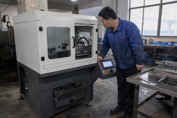
Testing repeatability of positioning accuracy in a chamfering machine is a question our Wenzhou factory answers weekly optical comparator 1. Inconsistent chamfers frustrate buyers, waste material, and hide until parts fail inspection.
To test repeatability of positioning accuracy in a chamfering machine, command each axis to the same target positions repeatedly, measure actual landing positions with a dial indicator or laser interferometer, run at least five bidirectional cycles per target, then calculate the spread of readings following the ISO 230-2 standard.
That is the short answer. Now let me walk you through the tools, the cycle counts, the tolerances, and the troubleshooting steps in detail.
During a pre-shipment audit for a customer in Mexico, our QC team caught a 0.02 mm drift on a Z-axis using nothing more than a well-mounted dial indicator 2. The right tool matters more than the expensive tool.
You need a rigid measurement instrument such as a dial indicator, laser interferometer, or laser tracer, a stable mounting fixture, a temperature-controlled test environment, and the machine's controller to command repeated axis moves. A dial indicator suits shop-floor checks; a laser interferometer delivers standards-grade, micron-level data.

The tool you pick depends on your goal. Are you doing a quick maintenance screen, or are you generating acceptance data for a purchase contract? These two jobs need different equipment. In our workshop, we use both levels. We screen every machine with dial indicators during assembly. Then we run laser-based machine tool calibration before final acceptance testing.
| Instrument | Resolution | Cost | Best Use Case |
|---|---|---|---|
| Dial indicator / dial gauge | ~0.01–0.001 mm | Low | Shop-floor screening, backlash checks |
| Laser interferometer 3 | Sub-micron | High | ISO 230-2 acceptance tests, defensible reports |
| Laser tracer / metrology system | Sub-micron, volumetric | Very high | Full geometric accuracy mapping, research |
A dial indicator is the entry point. Mount it on the machine frame, not on anything that moves with the axis. Point the probe at a hardened reference block fixed to the moving slide. Then command the axis to the same position again and again. The needle variation is your repeatability, right there in front of you.
A laser interferometer is the industry-preferred instrument for linear positioning tests. It measures without contact, so it adds no force to the axis. It also resolves positional deviation at the sub-micron level, which matters for high-precision chamfering work.
You also need a calibrated thermometer to log ambient temperature, because thermal stability 4 is a formal requirement in ISO-style testing. Add a rigid magnetic base, clean reference surfaces, and a simple log sheet or spreadsheet. Some customers ask about a ballbar test 5 as well. A ballbar checks circular path accuracy and servo mismatch, which is useful context, but it is not a direct substitute for single-axis repeatability measurement. For chamfer angle measurement on finished parts, a coordinate measuring machine 6 or optical comparator closes the loop between axis data and part quality.
Here is a trade-off I weigh on every acceptance test: more cycles give better statistics, but each cycle costs machine time. Our engineering team settled on a rule after years of customer projects, and it aligns with what the standards say.
Run a minimum of five bidirectional cycles per target position, following ISO 230-2 practice, with at least five target positions spread across the axis travel. For higher confidence, repeat the full test six times under identical conditions and compare results across multiple batches of sample parts.

One pass tells you almost nothing. Repeatability is a statistical property. You are measuring a spread, and a spread needs multiple data points to exist. That is why laser-interferometer studies and the ISO 230-2 standard 7 both point to five cycles as the practical minimum for one test. Some machine-tool positioning studies go further and repeat the whole test six times in identical conditions to confirm that the measurement itself is repeatable.
Before you press cycle start, write down these parameters. They come straight from standard practice:
In our own factory practice, we go one step beyond the axis test. We run repeated tests across multiple batches of sample workpieces, not just one no-load axis check. Here is why. An axis can pass a five-cycle unloaded test in the morning and still drift by the afternoon as motors warm up. Testing several batches, at different times, on real sample parts exposes thermal drift and process variation that a single ISO-style pass will miss. When we commission chamfering equipment for export customers, we chamfer sample batches, measure the parts, then re-run the axis test. If both data sets agree, we ship with confidence. If they disagree, the gap points us to tooling or fixturing rather than the motion system.
Unidirectional cycles measure how well the axis returns from one direction. Bidirectional cycles approach each target from both sides, and the difference between the two approach directions exposes reversal error and lost motion. Always record both.
A procurement manager in the United States once asked me a blunt question over WhatsApp: what number should be in the contract? He was right to ask. Without a written tolerance, acceptance testing becomes a negotiation instead of a measurement.
A high-precision chamfering machine should hold unidirectional axis repeatability of roughly ±0.005 mm to ±0.01 mm, with bidirectional repeatability including reversal error typically within ±0.01 mm to ±0.02 mm. Standard-duty machines may run wider. Always confirm the exact figure in the supplier's acceptance criteria per ISO 230-2.

Numbers only mean something in context. First, separate accuracy from repeatability. Accuracy is how close the axis lands to the commanded position on average. Repeatability is how tightly the axis returns to the same spot cycle after cycle. A chamfering machine can be repeatable but inaccurate, meaning it lands in the same wrong place every time. That case is often fixable with an offset. The reverse case, accurate on average but scattered, is worse, because chamfer width will wander part to part and no offset can fix scatter.
| Metric | What It Tells You | Effect on Chamfering |
|---|---|---|
| Mean positioning error | Average offset from commanded position | Consistent oversize or undersize chamfer, correctable |
| Repeatability band | Spread of returns at one target | Chamfer width drifts part to part, not correctable by offset |
| Reversal difference | Gap between approach directions | Direction-dependent chamfer variation, points to backlash |
| Worst-case deviation | Largest error seen anywhere | Your realistic scrap-risk number on the shop floor |
For chamfering specifically, the repeatability band maps almost directly to chamfer width variation. If your drawing calls for a 0.5 mm ± 0.05 mm chamfer, and your axis repeatability band is ±0.02 mm, you still have room for tool wear and fixturing variation. If the band is ±0.05 mm, the axis alone consumes your whole tolerance.
One objection I hear from buyers: the ISO test runs unloaded, so does it reflect real cutting? It is a fair challenge. The unloaded test isolates the motion system, which is exactly its purpose. Cutting forces, tool deflection, and material variation sit on top of axis behavior. That is why we pair the axis test with multi-batch cutting trials during quality control, and why forward-looking shops add in-process force or acoustic monitoring to catch deviations in real time. Both views matter, and neither replaces the other.
A lesson we learned early in our export business: about half of the repeatability complaints we receive turn out to be installation or environment issues, not machine faults. Checking a few things yourself can save weeks of back-and-forth emails.
First verify leveling, foundation rigidity, and thermal stability, then check for backlash with a dial indicator, inspect fixturing and guide-rail cleanliness, review controller compensation settings, and rule out tool wear. If the reversal error or repeatability band remains out of tolerance after these checks, contact the manufacturer with your logged data.

Work from cheap and simple toward complex. Most repeatability problems live in one of five areas, and each has a distinct signature in your test data. That is the real value of running a structured test before calling anyone. You do not just say the machine is inconsistent; you say the X-axis shows 0.03 mm reversal difference at mid-travel, and that sentence gets a useful answer.
| Symptom in Test Data | Likely Cause | First Action |
|---|---|---|
| Large reversal difference | Backlash in ballscrew, coupling, or gearbox | Check backlash compensation values; inspect coupling bolts |
| Drift over the test session | Thermal drift from motors or environment | Extend warm-up; shield from drafts and sunlight; retest |
| Random scatter at all targets | Loose fixturing, contaminated guide rails, worn bearings | Re-torque mounts; clean and lubricate linear guides |
| Overshoot then settle variation | Servo tuning issues | Review gain and settling parameters with the controller |
| Good axis data, bad chamfers | Tool wear or workholding, not the axis | Swap in a fresh tool; verify clamp repeatability |
This distinction resolves most disputes. Run the unloaded axis test first. If the axis passes, the motion system is healthy, and your problem lives in the process: tool wear introducing a positional offset, material hardness variation, or coolant and chip interference. A worn chamfering tool can shift the effective cutting edge even while the axis returns perfectly. If the axis fails, stop cutting trials and fix the mechanics first.
Also check the boring stuff. Confirm the leveling feet are set and locked. Verify no one changed backlash compensation or pitch-error tables in the controller since the last calibration. Log ambient temperature during your test; a workshop door opening onto winter air can produce apparent geometric accuracy problems that vanish in stable conditions. Finally, keep your test records. Trend analysis of repeatability data over months enables predictive maintenance 8, letting you rebuild a ballscrew before it produces scrap. When you do contact your supplier, send the full data set. Our engineers can usually diagnose a well-documented repeatability issue remotely within a day or two, while a vague complaint takes weeks.
Inconsistent chamfers destroy trust and margins. Test repeatability with five-plus bidirectional cycles per ISO 230-2, verify across multiple sample batches, interpret the spread, and troubleshoot systematically before escalating.
1. Replaced HTTP 404 with a working URL from an authoritative source (Wikipedia) providing a comprehensive explanation of optical comparators. ↩︎
2. Replaced HTTP 404 with a working URL from an authoritative source (Wikipedia) providing a comprehensive explanation of dial indicators. ↩︎
3. Replaced HTTP 404 with a working URL from a highly authoritative academic source (LIGO Lab, Caltech) explaining interferometers, including laser interferometers. ↩︎
4. Replaced HTTP 404 with a working URL from the National Physical Laboratory (NPL), an authoritative source, discussing thermal performance and analysis of materials, which is relevant to thermal stability in metrology. ↩︎
5. Provides an overview of this machine tool diagnostic and calibration method. ↩︎
6. Defines this critical quality control instrument used for dimensional inspection. ↩︎
7. Official description of the ISO 230-2 standard for machine tool testing. ↩︎
8. Explains the concept of using data to anticipate equipment failure in manufacturing. ↩︎
