

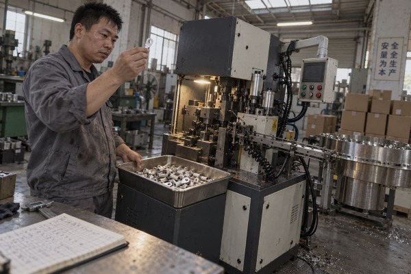
A buyer in Mexico asked our engineers how customization validation before mass production of cable lug making machines works. His last supplier showed one good sample, then shipped a drifting machine.
Confirm customization validation before mass production by running staged trials on the customized cable lug making machine: first-off samples, a multi-size engineering trial, a sustained repeatability run, and a documented Factory Acceptance Test, each measured against written drawing tolerances, named standards, and agreed yield targets.
That answer sounds simple. In practice, each stage hides decisions that decide whether your machine performs for years or fails in month two. Let me walk through them one by one.
Our QC team once caught barrel wall thickness drifting late in a trial run at our Wenzhou workshop. The first pieces had looked flawless.
Run four test groups before full-scale production: dimensional and visual checks on first-off samples, mechanical pull-out and electrical millivolt-drop tests against IEC 61238-1 or UL 486A-486B, a sustained repeatability run of around 500 pieces with beginning-middle-end sampling, and a changeover test across every lug size.

The central question is not "Does the machine make one acceptable lug?" The real question is whether it can repeat that result at the agreed speed, with your materials, across your whole product range. I treat validation as a staged approval, not a single demo.
These two are often confused. Prototype testing confirms that the lug design itself is sound. Pre-production sample validation confirms that this specific machine, with this die set customization and these process parameters, can reproduce that design repeatably. A customer can pass the first and still fail the second. So I always separate them in the test plan.
| Stage | What it proves | Sample scope | Key checks |
|---|---|---|---|
| First-off samples | Forming concept works | 5–20 pieces | Dimensions, burrs, cracks, plating, marking |
| Engineering trial | Usable process window | Several sizes, several settings | Vary pressure, dwell, feed speed, material batch |
| Repeatability run | Process stability | Around 500 pieces as a benchmark | Beginning, middle, end sampling; tool wear; drift |
| Acceptance run | Real production readiness | Full shift conditions | Planned speed, changeovers, operators, alarms |
The 500-piece figure is a starting benchmark, not a law. Order volume and product risk decide the final quantity.
A lug can look right and still fail under load. So I include pull-out testing with a defined conductor cross-section, strip length, insertion depth, and pulling speed. I also record the failure mode. Conductor pull-out, barrel splitting, and palm deformation tell very different stories about terminal crimping force calibration.
Electrical checks go beyond continuity. Contact resistance, millivolt drop under current 1, and temperature rise all matter. IEC 61238-1 test programs commonly describe 1,000 heating cycles to around 120°C with resistance checks during the test, and some qualification programs add short-time high-current tests that reach roughly 250°C. The exact numbers depend on the standard edition and the application, so I never copy them blindly into a contract.
A material compatibility test must use your real copper or aluminum batch. A machine that forms soft copper nicely may jam or crack harder stock. Datasheets cannot predict hardness variation between coils.
Some suppliers argue that a short sample run is enough because custom machine time is expensive. I understand the cost. But a short engineering trial followed by a statistically justified acceptance run is the compromise that protects both sides.
A procurement manager from the United States sent us photographs of a lug instead of drawings. We asked for controlled drawings before quoting the die set.
Verify sample conformity by measuring every critical-to-quality dimension on the controlled drawing with calibrated gauges or CMM, comparing results to the stated tolerances in a written inspection report, and checking that the supplier used your production-grade material, your approved die set, and the current drawing revision number.

Most customization failures I have seen start with incomplete specifications, not weak machine construction. If the supplier reads your product differently than you do, a successful trial validates the wrong product. So the drawing is where verification begins.
Before any sample is cut, both sides should sign one technical specification. It should list material grade, thickness, hardness, conductivity, plating type and thickness, cable cross-section range, barrel dimensions, stud-hole tolerances, palm geometry, marking, target speed, and maximum scrap rate. Any later change goes through a formal revision. Photographs and verbal descriptions do not count as controlled input.
I also map every customized feature to a named requirement. A lug can match your drawing yet not qualify under DIN 46235 2 for dimensions or under DIN 48083 for compatible crimping dies. The reverse is also true. Pick one primary governing standard and list the rest separately. Do not let the supplier choose whichever standard gives the easiest pass.
| Feature | Instrument | Why it matters |
|---|---|---|
| Barrel inner and outer diameter | Plug gauge, micrometer | Controls conductor fit and crimp result |
| Wall thickness | Micrometer or CMM | Thin walls split; thick walls raise resistance |
| Stud-hole diameter and edge distance | Pin gauge, caliper | Affects bolt fit and palm strength |
| Palm width, thickness, flatness | CMM, surface plate | Contact area and torque behavior |
| Overall and barrel length | Height gauge | Matches installation space |
| Burr height | Profile projector | Safety and insulation damage |
| Plating thickness | Calibrated XRF or cross-section | Corrosion and conductivity |
Photographs and uncalibrated hand tools are not acceptable evidence. Critical dimensions deserve 100 percent inspection during initial validation, then a defined sampling plan once capability is proven.
Here is a distinction I explain to every buyer. Accuracy asks whether one measurement is close to target. Repeatability asks whether the machine gives similar results under the same conditions. Process capability asks whether normal variation 3 stays inside the tolerance band. A sample that sits inside tolerance but near one limit is not robust. I use Cpk or a similar index during the sustained run to catch this.
Finally, confirm the mold design specifications and tooling drawings match the sample. Ask for the die inspection report and the material certificate for the raw stock used. Then keep a signed golden sample on both sides as the physical benchmark.
I learned early that a machine without paperwork becomes an orphan the moment a die wears out. Now every customized machine we ship carries a document pack.
Request a complete document pack: approved drawings with revision numbers, a signed technical specification, tooling drawings with die material certificates, raw-material and plating certificates, a Factory Acceptance Test report with pass/fail results, PLC recipe backups, a traceability log, a spare-parts list, and reference cases from similar customizations.

Documentation is not bureaucracy. It is the evidence that turns a demonstration into a validated process. I group the pack into four parts, and I ask for one more thing that most buyers forget.
This covers the controlled product drawings, the signed specification, and the die set drawings. Tooling deserves its own file because a machine can be capable on one product yet lose accuracy across a product family. I want the die material certificate, the hardness and expected service-life note, the die inspection report, and a spare-tooling list. I also want proof that dies are coded so an operator cannot install the wrong set.
Ask for the material certificate of the stock used in the trial. Chemical composition, conductivity, and hardness should be stated. Plating thickness should be measured by a calibrated method 4, not declared on a supplier letter. Where purity is critical, independent spectrometer verification is worth the fee.
The FAT must be agreed before shipment, never written afterward to fit a demo that already happened. Every line needs a test item, a method, a measured result, an acceptance limit 5, and a pass/fail mark. "Stable operation" and "good appearance" are not acceptance criteria. Cycle time, yield, scrap, pull-out force, resistance, pressure range, and interlock function all need numbers.
| Document | What it proves | When to receive it |
|---|---|---|
| Signed technical specification | Both sides agree on scope | Before tooling starts |
| Tooling drawings and certificates | Dies match the design | Before first-off samples |
| Material and plating certificates | Trial used production-intent stock | With each sample batch |
| FAT report | Machine met written criteria | Before shipment and final payment |
| PLC recipe backup and parameter list | Settings can be restored | At FAT |
| Traceability log | Batch links to tooling, material, operator | At FAT and ongoing |
| Reference cases | Supplier has done this before | During supplier evaluation |
PLC control system calibration records matter more every year. I ask for password levels, parameter limits, sensor-fault alarms, backup and restore steps, and recovery after power loss. Each finished batch should trace back to machine ID, tooling ID, material batch, recipe number, operator, date, and inspection results.
My strongest advice is to ask the supplier for case support. Request examples of similar customizations: the lug type, the material, the difficulties they met, and how they solved them. A supplier who has formed long-barrel aluminum lugs for a client in India or Vietnam will describe feed problems a brochure never mentions. Supplier data is useful for process control, but reference cases plus independent testing on high-risk products give you balanced evidence. Independent testing costs time, yet it removes the risk of approving incomplete results.
Every time we tune a crimping press, I weigh speed against stability. Pushing the production cycle time lower looks great in a quotation but can hide vibration and feed errors.
Identify performance issues by logging cycle time, hydraulic pressure, motor current, temperature, scrap categories, and alarms at fixed intervals during a long pilot run, sampling parts at the start, middle, and end, testing changeovers between sizes, and then repeating key checks at a Site Acceptance Test under factory utilities.

A short demonstration can hide instability. A long, logged pilot run evaluation exposes it. The purpose is to separate a machine that makes good samples from a machine that holds a stable process.
During the acceptance run I record data every fixed interval. A simple log works well.
| Timestamp | Recipe | Pressure | Cycle time | Output | Defects and category | Corrective action |
|---|---|---|---|---|---|---|
| 08:00 | Lug 70 mm² | Nominal | Target | — | — | Start of run |
| 09:00 | Lug 70 mm² | Nominal | Target | Count | Burr, 2 pcs | Check die edge |
| 10:00 | Lug 70 mm² | Slight drop | Slower | Count | Incomplete form, 1 pc | Verify hydraulic temperature |
| 10:30 | Changeover to 95 mm² | — | — | — | — | Record changeover duration |
Trends matter more than single readings. Rising oil temperature that slowly lowers forming pressure is a classic early warning. So is a changeover that takes twice the quoted time.
FAT happens at the supplier's plant. Site Acceptance Testing happens at yours. The difference is real. Voltage fluctuation, different compressed-air pressure, ambient temperature, tight floor space, and a different material-handling setup can all change results. The purchase contract should say clearly whether final payment depends on FAT, SAT, or both. I prefer both for customized lines.
For remote FAT, use multiple camera angles, live display of settings, visible sample labels, and calibrated tools on screen. Remote AR inspection of tool-change sequences is a helpful addition. But no video replaces physical samples shipped to you or to an independent lab.
AI vision systems can spot micro-fractures and barrel burrs invisible at forming speed. Digital twin simulation can predict die wear and tolerance drift before commissioning. Energy profiling per cycle gives a baseline for the hydraulic or electric drive under your specific load. These are useful supplements. They are not substitutes for the staged physical validation above.
Testing only one lug size. Using supplier-chosen stock. Measuring only first and last pieces. Ignoring tool wear. Treating speed as the only productivity measure. Skipping pull-out and resistance tests. Approving a video without samples. Releasing final payment with open deviations.
Approve when every acceptance item passes. Approve with corrective action when deviations are minor, documented, and dated. Reject when critical dimensions, safety interlocks, or mechanical and electrical results fail. Customization validation is complete only when the evidence covers dimensions, appearance, strength, electrical performance, productivity, safety, and traceability.
One good sample proves nothing. Staged trials, controlled drawings, a full document pack, and logged pilot runs prove readiness. Ask us for case support before you commit.
Interested in sourcing the products mentioned in this article? See details and request a quote here:
1. Official site for the IEC, which sets international standards for electrical testing and cable connectors. ↩︎
2. Official portal for German national standards, including specific requirements for electrical compression cable lugs. ↩︎
3. Leading authority on quality control metrics, providing standards for calculating process capability and statistical stability. ↩︎
4. NIST provides the foundational metrology and calibration standards used to ensure measurement accuracy in manufacturing. ↩︎
5. The International Organization for Standardization provides global benchmarks for quality management and acceptance criteria. ↩︎
