

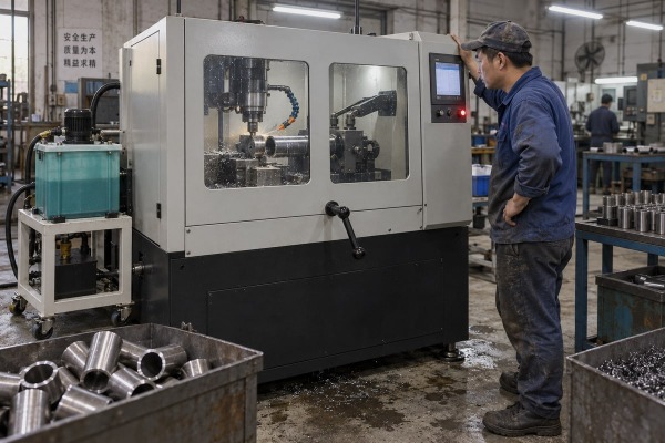
Buyers often ask our Wenzhou team whether a fully automatic chamfering machine 1 can hold a non-standard angle. Their fixed heads cut 45° only, and manual grinding eats margins.
Yes, a fully automatic chamfering machine can support custom chamfer angle settings, but the method varies. CNC or servo-controlled models accept angles digitally through an HMI. Others need manual guide adjustment or interchangeable cartridges, and some are limited by fixed-angle tooling.
That short answer hides a lot of detail. The word “automatic” describes the loading and cutting cycle. It does not always describe the angle change. Below, I walk through how the angle is set, what range you can expect, how batch switching works, and how to keep the result accurate. I will also explain why we added a servo controller 2 to our own heads for angle control and adjustment.
A procurement manager from Canada sent us a drawing with three angles on one part family. He wanted to know what "setup" really meant on our machine.
Setup depends on the machine type. On servo or CNC models, you enter the angle, chamfer width, depth, and feed on the touchscreen, then save it as a recipe. On mechanical models, you loosen the guide screws, align the head to a graduated scale, and retighten.

The first thing I tell buyers is this: there are four ways a machine can change its angle. Only one of them is truly digital. The other three involve hands, wrenches, or spare parts. Knowing which one you are buying saves a lot of frustration later.
| Method | How the angle changes | Changeover effort | Typical use |
|---|---|---|---|
| CNC or servo-programmed | Operator enters the value; a servo motor drive tilts or positions the head | Seconds, no tools | High-mix production, recipe-based lines |
| Adjustable tool holder | Head is tilted and locked by hand at marked increments | Minutes, hand tools | Repeat batches, medium mix |
| Interchangeable cartridges | A dedicated cartridge or guide set is swapped for each angle | 10–30 minutes, plus inventory | Pipe equipment needing almost any degree |
| Fixed-angle tooling | A cutter or grinding wheel ground to one angle is replaced | Tool change plus re-calibration | High-volume, single-angle parts |
A machine from the second or third row can still be called "fully automatic." The feeder, the pneumatic clamping mechanism, the cut, and the unloading all run without an operator. Only the angle change is manual. One machine manual I have read describes exactly this. You loosen four Allen screws, line the guides up with a scale, and tighten them again. That works, but it is not a recipe change.
When we were developing our chamfering line for metal pipe processing 3, our engineers kept seeing the same request. Customers wanted the angle to follow the drawing, not the cutter. So we added a servo controller dedicated to angle control and adjustment. The servo axis sets the head inclination. The PLC control system stores that value with the rest of the job. The operator never touches the guides.
One caution. Even with a servo axis, the carbide cutting tools 4 still have a face geometry. If the insert is ground for a 45° form, the axis can change size but not the form. We match the insert to the angle family before shipping. That is part of our tooling and sample-testing service, and it is why we ask for drawings up front.
Every time we quote a wider angle range, we weigh it against cutter clearance and edge strength. A broad range sounds impressive, but tooling sets the real limit.
Most programmable machines cover 30° to 60°, while compact units may offer 15° to 45° and high-end models up to 15° to 60°. The usable range still depends on the installed cutter, workpiece diameter, internal clearance, and whether you are deburring or weld beveling.

I want to be honest about ranges. A brochure number is a nominal value. The number that matters is the angle your part needs, at your diameter, with the tool installed. Here is how the common ranges line up with real work.
| Angle range | Typical application | Notes from our experience |
|---|---|---|
| 45° standard | General deburring and edge breaking | Most inserts are ground for this; fastest cycle |
| 30°–45° | Small components, fittings, inner and outer edge prep | Compact grinding units often stop here |
| 30°–60° | Pipe and tube weld beveling, CNC pipe end finishing | The range we design most tube heads around |
| 15°–45° | Some compact or manual-adjustment machines | Lower angles cut shallower depth |
| 30°–37.5° | Butt-weld preparation | 37.5° is common for structural and process piping |
If your drawing calls for a 37.5° bevel, the machine must hit that value, not round to 45°. Welding procedures define the root face and included angle. The chamfering machine must serve the weld, not the other way around.
This is the confusion I see most often. Buyers read "adjustable chamfer size" and assume "adjustable angle." They are different.
A CNC axis can control depth and width through feed. The angle may still be fixed by the cutter. One gear-chamfering specification I keep on file says it plainly: the tool decides the form, the axis decides the size.
The angle also limits depth. One machine manual lists a maximum chamfer depth of 5 mm, but only at 45°. Lower angles give lower depths. So a change from 45° to 30° does more than change the look. It changes material removal, tool load, and cycle time.
Our servo-controlled head handles an adjustable beveling angle within the range we test for each diameter band. When a buyer needs an angle near the limit, we cut sample parts first and send measurement reports before we confirm.
During a sample test for a hydraulic fitting customer, our line ran 30°, 37.5°, and 45° parts back to back. The only change was a recipe call on the screen.
Yes, if the machine has recipe storage. A PLC or CNC controller saves angle, depth, feed, and speed under a product name. Operators recall the preset in seconds, and a servo-driven head moves automatically. Mechanical machines still need manual guide or cartridge changes between batches.

Batch switching is where the servo controller pays for itself. In a high-mix shop, the cost is not the cut. The cost is the changeover. Every minute the line sits idle while someone loosens screws is a minute of lost output.
A recipe is more than an angle. On our controller, one saved job holds:
The operator picks the part number, confirms the tool, and runs. If the next batch uses the same insert family, there is no physical change at all. If it needs a different form, the screen prompts a tool swap.
| Approach | Angle change | Typical changeover | Risk of setup error |
|---|---|---|---|
| Recipe recall with servo head | Automatic | Under one minute | Low; values are validated once |
| Mechanical guide adjustment | Manual, by scale | Several minutes to tens of minutes | Medium; depends on operator reading |
| Cartridge or cutter swap | Manual, by part | 10–30 minutes plus alignment | Medium; new tool needs a first-off check |
A buyer in the United States once pushed back on this. His argument was fair. He runs millions of identical parts at 45°. A fixed tool is cheaper, simpler, and has nothing to misprogram. I agreed with him. If your product mix is one angle forever, a dedicated head wins on cost and maintenance. We still build that version.
The flip side is that flexibility adds some complexity. A programmable system needs validated recipes, operator training 5, and periodic calibration. We address that with a locked recipe library. Only a supervisor password can edit a validated job. Operators can run jobs but not rewrite them. That keeps the error rate close to the fixed-tool case.
Newer systems push this further. CAD-to-machine synchronization can send angle parameters straight from the design file to the controller, removing manual entry. Digital twin tools can simulate the toolpath at a new angle to check for collisions before the head moves. Vision systems are starting to read a cast edge and suggest an angle that compensates for irregularity. We are watching these closely for our custom automation projects, but the servo head and recipe library remain the practical core for deburring and beveling lines today.
One lesson stuck with our engineers early on: a servo axis that reads 37.5° means little if the clamp lets the tube drift. Accuracy lives in the whole chain.
Consistency comes from controlling the whole process chain: rigid clamping, true workpiece centering, low tool runout, servo positioning with wear compensation, and routine calibration. Verify first-off parts with a profile projector or gauge, then run in-process checks at every angle you use, not just 45°.

Angle customization is only worth paying for if the machine repeats it. A head that can be programmed to any value but drifts by a degree between batches is worse than a fixed 45° tool. So I want to break accuracy down into its sources and its checks.
| Error source | Effect on the chamfer | How we control it |
|---|---|---|
| Clamp movement | Angle and width vary part to part | Pneumatic clamping sized for the diameter; pressure saved in recipe |
| Off-center workpiece | Uneven chamfer around the circumference | Self-centering jaws; centering check at setup |
| Tool runout | Width changes, chatter marks | Dial check on the spindle; carbide cutting tools seated and torqued |
| Head positioning | Angle offset from commanded value | Servo motor drive with encoder feedback; scale calibration |
| Tool wear | Angle holds, width and depth shrink | Wear compensation offset in the controller |
| Head flex at extreme angles | Angle shifts under load | Reduced feed near range limits; rigidity tested per diameter band |
Automatic feeding raises throughput. It does not prove geometry. We recommend layering checks:
The key is to inspect at the angles you use. A machine can hold 45° perfectly and still wander at 30°. When we commission a line, we cut samples at the minimum, midpoint, and maximum angles the customer plans to run. The reports go to the buyer before the machine leaves our factory.
If a supplier only shows a 45° sample, ask for more. That single request filters out a lot of overstated brochures.
Angle flexibility is real, but only when it is verified. Ask how the angle is set, what tooling it needs, and demand samples at your angles before you buy.
Interested in sourcing the products mentioned in this article? See details and request a quote here:
1. ISO provides international standards for machine tool safety and performance. ↩︎
2. IEEE provides standards for electronic controllers and servo motor drives in machinery. ↩︎
3. ASME sets standards for metal pipe processing and pressure piping components. ↩︎
4. Wikipedia provides technical background on cemented carbide materials used in cutting tools. ↩︎
5. OSHA provides guidelines on operator training and safety for industrial machinery. ↩︎
