

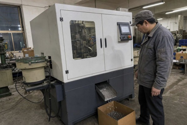
A fully automatic chamfering machine’s speed range can make or break your line. I’ve watched buyers chase catalog RPM, then hit bottlenecks. Our Wenzhou workshop solves that mismatch daily through customization.
A fully automatic chamfering machine’s speed range fits your production process when its cycle time, feed rate, and changeover speed match your line’s output target. Typical machines run 300–8,500 RPM, with cycle times from 2.5 to 15 seconds per part, and speed settings are usually customizable.
Speed is a system question, not a single spec. Below, I break down how to match speed to output, materials, customization options, and overall efficiency.
A procurement manager from the US once sent me only one question: "What's the max RPM?" Our team replied with a different number first — his required parts per hour.
Match the machine's speed range to your line by working backward from target output. Calculate required pieces per hour, add changeover and downtime buffers, then confirm the machine's real cycle time — not just spindle RPM — meets or slightly exceeds that throughput demand.

Raw spindle speed tells you very little on its own. What matters is production throughput: how many finished, in-spec parts leave the machine every hour of a real shift. In our experience building metal processing machines for export markets like the US, India, and Vietnam, the mismatch almost never comes from RPM. It comes from feed rate, part loading, and changeover time.
First, write down your target pieces per hour. Then check it against typical performance bands for automatic chamfering equipment:
| Machine Type | Typical Speed Range | Typical Cycle Time | Best Fit |
|---|---|---|---|
| High-volume bar/fastener chamfering | Up to 3,000 RPM | ~2.5 seconds per operation | Mass production of small parts |
| General automatic chamfering | 2,200–8,500 RPM | Under 15 seconds per piece | Rods, studs, small tubes |
| Heavy chamfer / weld prep | 300–1,500 RPM | Longer, torque-driven cycles | Thick walls, large bevels |
| Double-end chamfering systems | 500–3,000 RPM | 3–4 seconds for both ends | Tubes and bars needing both ends finished |
Second, look at the handling system. A vibratory bowl feeder 1, like the one we mount on our own units, keeps parts flowing continuously. If your upstream cutting station delivers parts slower than the chamfering cycle, the machine will simply wait. Third, factor in changeover. Some compact systems change part sizes in about 45 seconds; others need much longer. For high-mix production, changeover-adjusted output is the honest metric. When we quote equipment, we always ask for the customer's part mix before we ever discuss spindle speed.
During a sample test for a Vietnamese cable lug producer, we ran the same chamfer program on brass and stainless steel. The stainless parts chattered badly until we dropped the spindle speed by nearly a third.
Adjust speed settings based on material hardness, part diameter, wall thickness, and chamfer depth. Harder alloys like stainless steel need lower spindle speeds and slower feed rates to protect tools; softer materials like aluminum and brass tolerate high-velocity cutting for faster cycles.

Material hardness is the single biggest driver of speed settings. Cutting too fast on a hard alloy burns tool edges, creates chatter, and ruins surface finish 2. Cutting too slow on soft material wastes cycle time and can smear the edge instead of shearing it cleanly.
Here is how we typically think about the main factors when we calibrate equipment before shipment:
| Factor | Effect on Speed Setting | Practical Guidance |
|---|---|---|
| Material hardness | Harder = slower spindle speed | Stainless and hardened steel run at the low end of the range |
| Part diameter | Larger = lower RPM for same surface speed | Keep cutting speed constant, not RPM |
| Wall thickness | Thin walls = gentler feed rate | Prevents deformation on tubes |
| Chamfer depth | Deeper cuts = more torque, less speed | Big weld bevels favor 300–1,500 RPM machines |
| Tool material | Carbide tolerates higher speeds | Match insert grade to alloy |
Harmonic vibration, or chatter, appears when speed and rigidity fall out of balance. It leaves wavy marks on the bevel and shortens tool life fast. If you hear a changed pitch or see a rougher edge, step the spindle speed down and retest. There is also a real trade-off between velocity and tool life. Running at the top of the speed range boosts parts per hour but accelerates tool degradation 3, which means more downtime for tool changes. Our engineers usually recommend running at roughly 80–90% of the proven maximum for a given material. That small sacrifice in cycle time often pays back in fewer stoppages and more consistent quality across a full shift.
The trade-off we weigh most often in our engineering meetings is standardization versus fit. A standard speed band keeps cost down. A customized speed range keeps your line balanced. For most B2B buyers, the second wins.
Yes, the speed range can be customized. Reputable builders adjust spindle speed via variable frequency drives or servo motor drives, program feed rates through the PLC control system, and tailor tooling, fixtures, and feeders to your part drawings and target cycle time.

Customization is exactly where our team in Wenzhou spends most of its R&D hours. When a customer sends product drawings and describes their production process, we do not just pick a machine off a shelf. We size the motor, select the drive type, and configure the control logic 4 around their actual parts. That is the core of our OEM/ODM work on metal processing machines and industrial automation systems.
Before shipment, we run sample testing with the customer’s actual parts and record the validated speed settings. That way the machine arrives with a proven starting recipe, not a blank slate. For buyers who worry about installation and commissioning, this step removes most of the risk.
A lesson I learned early in exporting equipment: one customer doubled spindle speed to chase output, and his reject rate tripled within a week. Faster is only better when quality holds.
Machine speed raises production efficiency by cutting cycle time and labor cost per part, but excessive speed causes chatter, poor surface finish, faster tool wear, and more rejects. Peak efficiency comes from the speed that maximizes good parts per shift, not raw output.

Speed touches every efficiency metric you track. It shortens cycle time, which raises hourly output. It reduces labor cost per part 6, because one operator can supervise an automatic cell instead of hand-finishing edges. Compared to a manual deburring process, a well-set automatic machine delivers consistent chamfer angles part after part, which downstream assembly and welding stations depend on.
But every speed increase pulls on quality and cost. Here is the relationship in simple terms:
| Speed Level | Efficiency Effect | Quality Effect | Hidden Cost |
|---|---|---|---|
| Below optimal | Wasted capacity, longer cycles | Good finish, possible edge smearing on soft metals | Higher labor cost per part |
| Optimal band | Maximum good parts per shift | Clean, consistent chamfers | Balanced tool wear |
| Above optimal | More parts per hour on paper | Chatter, rough bevels, dimensional drift | Rapid tool wear, rework, downtime |
Start at the material-recommended speed. Run a batch, measure surface finish and chamfer dimensions, and log tool wear. Increase speed in small steps until quality or vibration degrades, then back off one step. Advanced setups can help here: some next-generation systems use sensor feedback to automatically reduce speed when material hardness spikes or tools dull, protecting quality without operator intervention. Energy matters too. Running at an efficient point on the power-to-speed curve lowers the kilowatt-hour cost 7 per processed unit — a small saving per part that compounds across millions of parts. In our after-sales support, we help customers fine-tune these settings remotely, because a stable, well-tuned speed profile is what turns a fast machine into a profitable one.
Speed range fits when cycle time, feed rate, and changeover match your line — and yes, it can be customized. Send us your drawings, and we'll validate the numbers together.
1. Explains the parts-feeding technology used to keep chamfering machines running continuously. ↩︎
2. Authoritative Wikipedia entry explaining surface finish and texture standards. ↩︎
3. Comprehensive Wikipedia guide on tool wear mechanisms in machining. ↩︎
4. IEEE publishes standards and research on industrial control logic and automation engineering. ↩︎
5. Background on programmable logic controllers that manage speed and feed recipes. ↩︎
6. Reliable economic definition of labor costs per unit of production. ↩︎
7. IEA provides energy efficiency data relevant to power-to-speed cost analysis in manufacturing. ↩︎
