

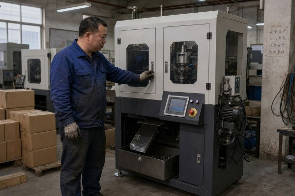
Choosing the wrong spindle power for an automatic chamfering machine wastes money fast specific cutting energy 1. On our production line in Wenzhou, I have seen buyers overpay for kilowatts they never use.
Automatic chamfering machines for electrical hardware components typically need 0.75 kW to 2.2 kW of spindle power. Small terminals and connectors run well on 0.55–1.1 kW, while wide copper busbars and heavy-duty CNC chamfering systems require 3.7 kW or more.
That range is a starting point, not a final answer. The right number depends on your material, your chamfer size, and your production speed. Let me walk you through each factor.
Last year, a customer sent us identical terminal drawings in two versions: one in C1100 copper, one in 6061 aluminum 2. Our engineers specified different spindle setups for each.
Copper electrical hardware usually needs 1.1–2.2 kW spindle power because it is gummy and demands higher torque. Aluminum parts of the same size chamfer cleanly at 0.55–1.1 kW, but they need higher spindle speed (RPM) for a smooth, burr-free finish.

Copper and aluminum behave very differently under a chamfering cutter. Copper is soft on a hardness chart, but it does not cut like a soft material. It smears, sticks to tooling inserts, and generates long, stringy chips. That sticky behavior raises cutting force 3, so the spindle needs extra torque to keep the chamfer angle consistent across a full production shift. Aluminum is the opposite. It shears cleanly and produces short chips. The challenge with aluminum is not force. It is surface finish 4. Low spindle speed on aluminum leaves smearing and micro-burrs that later interfere with cable insulation seating or plating quality.
Here is how I explain it to buyers who compare the two metals:
| Factor | Copper (C1100, C11000) | Aluminum (6061, 1060) |
|---|---|---|
| Typical spindle power | 1.1–2.2 kW | 0.55–1.1 kW |
| Preferred spindle speed (RPM) | 1400–2800 r/min | 2800 r/min or higher |
| Main challenge | High cutting force, sticky chips | Burr control, surface finish |
| Tooling insert wear | Faster (built-up edge) | Slower with polished inserts |
| Coolant or air blast | Recommended | Often optional |
My own rule from years of building these machines: the exact power still has to be confirmed against material hardness and the machining dimensions of the actual part. A wide copper busbar edge can demand more spindle power than a small stainless connector, simply because the engaged cutting width is larger. Never size the spindle from the material name alone. Size it from material plus the real chamfer cross-section you must remove.
A procurement manager from the US once asked me to quote a machine by kilowatts alone. I asked him for three numbers instead: part thickness, chamfer size, and parts per hour.
Calculate spindle power from material removal rate: multiply chamfer cross-section area by feed rate, then by the material's specific cutting energy. Add 30–50% headroom for tool wear and continuous duty. Higher production volume means faster feed, which directly raises the required kW.

The math behind spindle sizing is simpler than most buyers expect. A cutting force calculation starts with how much metal you remove per second. A 0.5 mm chamfer on a 2 mm thick terminal removes very little material, so even at high cycle rates a compact 0.75 kW spindle handles it. A 3 mm chamfer on a 10 mm thick copper busbar removes many times that volume, and the power requirement climbs quickly.
Many small motors are rated S6, meaning intermittent load. An automated line with an automatic feeding system runs the spindle almost nonstop. For that, you want an S1 continuous rating at your calculated load. When we commission machines for high-volume terminal producers, we verify the motor stays within temperature limits over a full eight-hour test run, not just a five-minute demo. This is also why our quotes always separate spindle motor power (kW) from total connected load. A machine listed at 12 kW total may carry only a 3.7 kW cutting spindle, with the rest going to servo axes, clamping, and feeding.
The trade-off I weigh most often in design reviews is rigidity versus raw power. Buyers assume a bigger motor cuts better. Our test bench tells a different story.
No, higher spindle power alone does not improve chamfering precision. Precision on terminals and electrical connectors comes from spindle runout, machine rigidity, fixturing, and feed control. An oversized spindle can even add vibration and heat, hurting micro-chamfer consistency on small parts.

Precision machining and power solve different problems. Power determines whether the cutter can remove material at your target feed without stalling. Precision determines whether the chamfer angle, depth, and finish repeat within tolerance from part one to part ten thousand. On small electrical connectors, the material removal is tiny. A 0.55 kW spindle already has more than enough force. What decides quality is everything around the spindle.
Runout is first. If the spindle wobbles even 0.02 mm, the chamfer depth varies around the edge. Second is rigidity. The spindle housing, linear guides, and ball screw drive must resist deflection under cutting load. Third is fixturing. If the pneumatic clamp lets a thin terminal shift by a hair, no spindle can fix that. Fourth is feed control. Servo-driven feed holds a constant chip load, so every edge sees the same cutting condition.
There is one indirect link between power and precision worth naming. An underpowered spindle slows down under load. That RPM drop changes chip formation mid-cut and leaves an inconsistent edge that then needs manual deburring. So the goal is sufficient power with headroom, not maximum power. When we build CNC chamfering machines for connector producers, we often pair a modest 1.5 kW servo spindle with heavy castings and precision alignment blocks. Customers running mixed batches also benefit from programmable spindle speed, since switching between brass, copper, and aluminum parts calls for different RPM, not different horsepower. Vision inspection downstream will flag any chamfer inconsistency, and in our experience, the root cause is almost never a lack of kilowatts.
When Michael, a procurement manager we work with in North America, sent us drawings for a cable lug line, our first deliverable was not a quote. It was a spindle sizing sheet.
YQUNIQUE recommends 0.75–1.1 kW spindles for small terminals and connectors, 1.5–2.2 kW for cable lugs and mid-size copper parts, and 3.7 kW or higher servo spindles for busbar chamfering. Final power is confirmed against your part drawings and sample tests.

Because we design custom equipment rather than sell one fixed catalog model, our recommendations follow the part, not the other way around. Here is the sizing guide we use as a starting point in project discussions:
| Component type | Typical material | Recommended spindle power | Typical spindle speed | Notes |
|---|---|---|---|---|
| Small terminals, pins | Brass, copper alloy | 0.55–0.75 kW | 2800 r/min | Prioritize low vibration |
| Electrical connectors | Copper, aluminum | 0.75–1.1 kW | 1400–2800 r/min | Dual-speed motors work well |
| Cable lugs, mid-size parts | Copper, aluminum | 1.5–2.2 kW | 1400–2800 r/min | Dual-station setups common |
| Copper busbars | Hard copper | 3.7 kW+ servo | Programmable | Total machine load 10–12 kW |
| Steel hardware, heavy deburring | Steel, stainless | 3–4 kW+ | Lower RPM, high torque | Consider carbide tooling inserts |
Our process is straightforward. First, we review your drawings and confirm material grade, hardness, and chamfer dimensions. My standing rule inside our engineering team is that the exact power must be verified against material hardness and machining size, never assumed from part category. Second, we run sample tests on your actual parts and record spindle load, cycle time, and edge quality. Third, we adjust tooling geometry and chamfer angle programming before finalizing the build. Fourth, we integrate the automatic feeding system and clamping, then verify the spindle holds its rated load through continuous operation.
We also specify compressed air requirements alongside motor power, since pneumatic clamping and chip evacuation are part of the real installed footprint. For buyers comparing quotes, ask every supplier for the spindle drive power, the total connected load, and the duty rating separately. Those three numbers, together, tell you what the machine can really do on your line.
Undersized spindles stall and burr; oversized ones waste budget. Match spindle power to material, chamfer size, and cycle time — then confirm with sample tests before you buy.
1. Discusses the concept and calculation of specific cutting energy in material removal. ↩︎
2. Details the properties, applications, and characteristics of 6061 aluminum alloy. ↩︎
3. Explains the definition, measurement, and importance of cutting force in machining. ↩︎
4. Defines surface finish, its characteristics, and its role in manufacturing processes. ↩︎
