

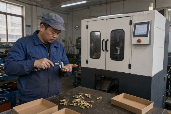
A failed fully automatic chamfering machine sample test can freeze your whole project. On our production line in Wenzhou, I have seen that panic firsthand — and solved it.
If a fully automatic chamfering machine sample test fails, stop the run, measure the defect, then check tooling, machine settings, workholding, and material in that order. Adjust one parameter at a time, retest, and contact your supplier for online commissioning guidance if the failure repeats.
That is the short answer. Now let me walk you through the full process, step by step, the same way we guide our own customers after delivery.
Last year, a customer in Vietnam sent me photos of uneven chamfers on brass terminals. Our team traced it to a worn insert in under an hour — not the machine itself.
The most common reasons a chamfering machine sample test fails are worn or wrong cutting tools, incorrect feed rate or spindle speed, poor workpiece clamping, spindle runout, CNC programming errors, and material inconsistency. Most failures come from setup and tooling, not fundamental machine defects.

Before you touch a single parameter, you need to know what type of failure you are looking at. In my experience supporting buyers across India, Mexico, and the US, a failed sample almost always falls into one of four symptom groups. Each group points to different root causes.
A wrong-size chamfer usually means an offset error, a tool diameter mismatch 1, or a CNC programming error. An uneven chamfer across parts points to spindle coaxiality deviation 2, worn clamping jaws, or feeding-position drift. A rough edge finish suggests tool wear, contamination, or bad cutting parameters 3. Vibration and noise point to loose fasteners or an unstable base.
Here is the mapping we use during after-sales calls:
| Failure Symptom | Most Likely Causes | First Thing to Check |
|---|---|---|
| Wrong chamfer size | Offset error, wrong tool, program error | Tool offsets and drawing spec |
| Uneven chamfer | Spindle runout, worn jaws, feed drift | Workpiece alignment and clamp wear |
| Rough surface finish | Dull insert, wrong speed/feed, chips | Tool wear analysis 4 and cleanliness |
| Vibration or noise | Loose bolts, poor installation | Fasteners and machine leveling |
| Overheating or stalls | Overload, lubrication, power supply | Load settings and lubrication points |
In our workshop, tool wear analysis is always step one. A dull or chipped insert will ruin chamfer quality no matter how perfect your program is. Also confirm the correct insert type for your material. Soft aluminum and hardened steel need different edges. Check that mounting bolts are tight and that no chips or dust have created gaps in the holder.
Workpiece alignment issues and low clamping rigidity are the silent killers. If the part shifts even slightly during cutting, the chamfer angle drifts. Worn collets, dirty jaws, and wrong clamping pressure settings 5 all cause this. Deburring quality control on the incoming blanks matters too — a burr under the jaw tilts the whole part.
There is a trade-off I weigh every time we commission a machine: adjust parameters first, or question the workpiece first? Getting this call wrong wastes hours and scraps good blanks.
Run a controlled comparison. Machine a verified reference sample with known hardness and dimensions. If the reference part passes, your material is the problem. If it also fails, the issue lies in machine settings, tooling, or calibration — not the workpiece.

This single test saves more time than anything else I can recommend. When we run sample tests for customers before shipment, we always keep a batch of certified reference blanks on hand. They give us a clean baseline. Without a baseline, you are guessing.
Settings problems produce consistent, repeatable defects. Every part fails the same way. The chamfer is always 0.2 mm oversized, or the finish is always rough on the same edge. That consistency is your clue. Check these items in order:
Material problems produce random, inconsistent defects. One part is fine, the next chatters. This happens when blank hardness varies between batches, when surface oil or oxidation contaminates the cut, or when blank diameter tolerance is loose. Material hardness testing 7 on a few samples from different batches will confirm variation quickly.
| Indicator | Points to Settings | Points to Material |
|---|---|---|
| Defect pattern | Identical on every part | Random across parts |
| Reference blank result | Also fails | Passes cleanly |
| Hardness readings | Uniform | Varies batch to batch |
| Surface condition | Clean blanks still fail | Oily or oxidized blanks fail |
| Tool wear rate | Normal | Abnormally fast |
Whatever you find, change only one variable per retest. Our engineers have learned this the hard way. If you adjust speed, feed, and clamping pressure all at once, you will never know which change worked — or which one created a new problem.
A procurement manager from Canada once messaged me at midnight, frustrated after three failed retests. Ten minutes of the right questions on WhatsApp fixed what three days of tweaking could not.
Ask your supplier for the exact commissioning parameters used during their factory sample test, the recommended tool and insert specification for your material, acceptable spindle runout tolerance, correct clamping pressure settings, and whether they offer live online guidance during your retest.

When we ship a fully automatic chamfering machine from our Wenzhou factory, we always run a sample test with the customer's own material before packing. Those factory parameters are gold. If your machine passed testing at the supplier's site but fails at yours, something changed in transit or setup — and the supplier's records tell you what "correct" looks like.
Do not send a vague complaint like "the machine doesn't work." Send data. Then ask targeted questions:
When samples fail at a customer's site, our standard response is online commissioning support. We guide the operator through parameter adjustment on a video call, watch the actual cut, and listen to the machine sound. An experienced engineer can hear a dull tool or a loose clamp. That remote session usually resolves the issue in one or two retest cycles. Before you sign any purchase contract, confirm this level of after-sales support is included — not every supplier offers it, and the difference shows exactly at moments like this.
Photos help, but numbers solve. Measure the actual chamfer size, angle, and surface finish requirements against the drawing. Send the deviation values. A supplier who knows the error is "+0.15 mm on chamfer width" can calculate the exact offset correction instead of guessing.
Every failed sample teaches us something. Over years of exporting metal processing machines to ten countries, we have turned those lessons into a pre-run discipline that our customers now follow too.
Prevent future sample test failures by locking in a pre-run checklist: verify tool condition and mounting, confirm material specs match the tooling, warm up the spindle, check clamping and alignment, validate the program on one part, and keep a maintenance and calibration log.

Prevention is cheaper than troubleshooting. A ten-minute pre-run routine costs almost nothing. A failed sample batch can cost you scrapped material, a delayed customer shipment, and hours of diagnostic work. Here is the system I recommend.
Treat every sample test like a process validation step, not a "try it and see" run. Our engineers use a checklist similar to this before any customer acceptance test:
| Check Item | What to Verify | Frequency |
|---|---|---|
| Tool condition | No wear, chips, or dullness beyond tolerance | Every run |
| Tool mounting | Correct bolts, tight holder, no debris gaps | Every run |
| Material match | Hardness and grade match the tooling spec | Every batch |
| Clamping system | Jaw wear, cleanliness, correct pressure | Every run |
| Thermal soak | Spindle warmed to stable temperature | Every cold start |
| Program validation | Single-part trial before batch run | Every new program |
| Guides and gears | Chip buildup removed, lubrication topped up | Daily/weekly |
Many repeat failures come from incoming blanks, not the machine. Set incoming inspection rules. Spot-check hardness on new batches. Reject blanks with heavy oxidation or oil films. Consistent material makes feed rate optimization actually stick from one order to the next.
Keep a simple log: date, material batch, tool hours, parameters used, and measured results. When a problem appears, the log shows you what changed. It also makes conversations with your supplier faster, because you can send history instead of memory.
The best-calibrated machine still fails under an untrained hand. When we deliver custom automation equipment, we include operation training and documented calibration steps. Ask your supplier for the same. An operator who understands spindle speed adjustment and tool wear analysis catches problems before they become failed samples.
A failed sample test is stressful, but rarely fatal. Diagnose by symptom, isolate settings from material, involve your supplier early, and prevent repeats with disciplined checks.
1. Authoritative reference for milling cutter types, geometries, and diameter specifications. ↩︎
2. Explains the technical concept of runout and deviation in rotating mechanical systems. ↩︎
3. Comprehensive Wikipedia overview of machining speeds, feeds, and cutting parameters. ↩︎
4. Detailed Wikipedia entry covering tool wear mechanisms and analysis in machining. ↩︎
5. Technical engineering resource for calculating and setting proper clamping forces. ↩︎
6. Industry leader resource for calculating and optimizing cutting speeds and feeds in milling. ↩︎
7. Describes standardized methods for measuring the resistance of industrial materials to permanent deformation. ↩︎
