The Broad Prospects of Aluminum Profiles and the Key Role of Automatic Aluminum Cutting Machines
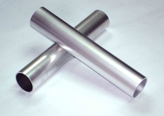
Aluminum profiles, known for their lightweight, high strength, corrosion resistance, and ease of processing, have become an indispensable material in modern industry.
They are widely used in various sectors such as construction, transportation, automotive, and energy.
With the global economic recovery and continuous technological advancements, the aluminum profile industry is facing unprecedented opportunities for development.
Development Prospects of the Aluminum Profile Industry
1. Continuous Market Demand Growth
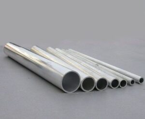
With the advancement of industrialization and urbanization, the market demand for aluminum profiles continues to rise. Particularly in sectors such as construction, transportation, automotive, and energy, the application scope of aluminum profiles is expanding. Data shows that in 2023, China’s aluminum profile production was approximately 21.8 million tons, an increase of 9% year-on-year. It is expected that production will exceed 22 million tons in 2024.
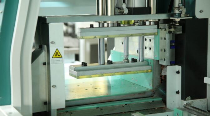
2. Technological Innovation Drives Industrial Upgrading
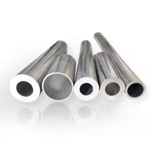
The aluminum profile industry is upgrading through the introduction of advanced production processes and equipment, significantly improving product precision, strength, and durability. For example, the development of new alloys and the progress of precision processing technologies have not only enhanced the performance of aluminum profiles but also expanded their application range.
3. Green and Sustainable Development
Amidst the growing global environmental awareness, the aluminum profile industry is moving towards green and sustainable development. Companies are increasingly adopting low-carbon and eco-friendly production methods and developing recyclable aluminum profile products.
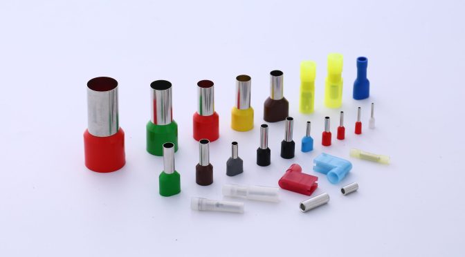
4. Diversified Application Fields
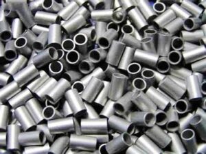
The application fields of aluminum profiles are continuously expanding, especially in emerging areas such as new energy vehicles, photovoltaics, and aerospace, where the demand for high-quality and high-performance aluminum profiles is increasing.
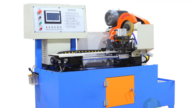
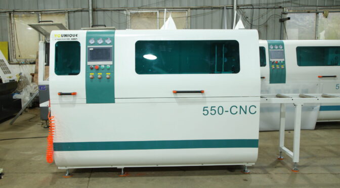
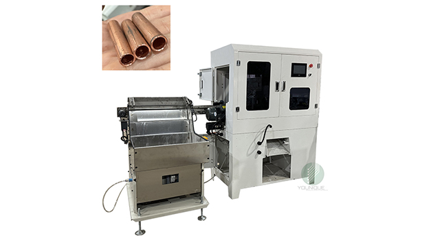
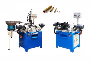
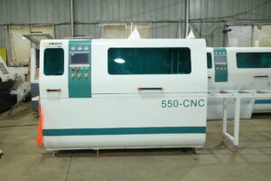
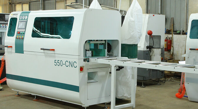
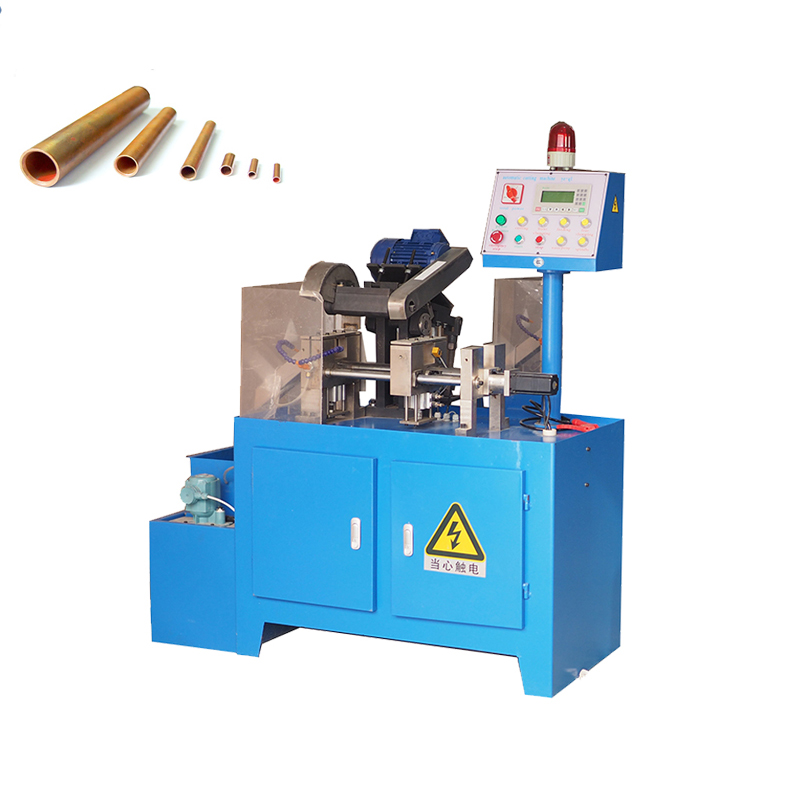
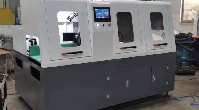
The Key Role of Automatic Aluminum Cutting Machines
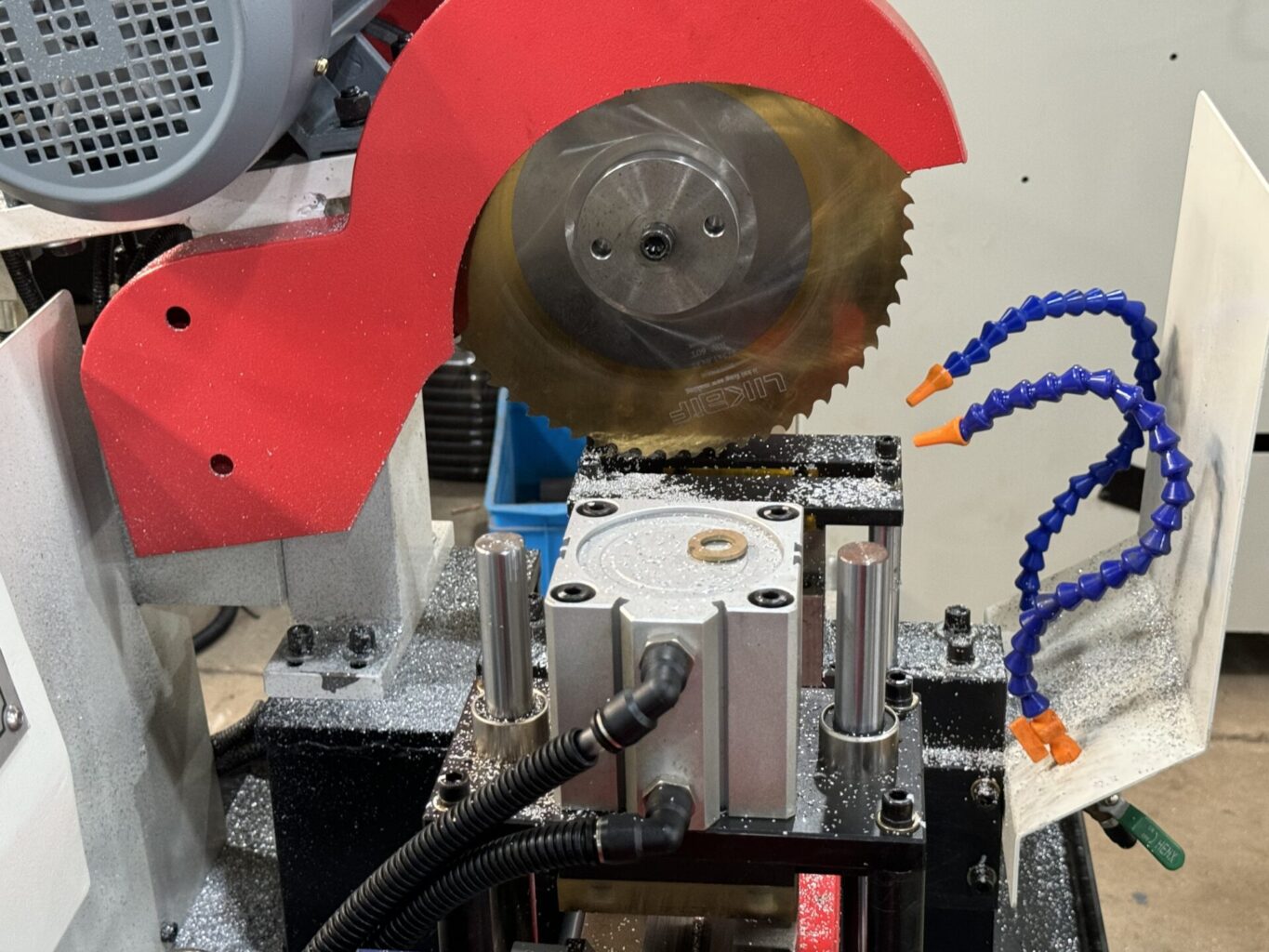
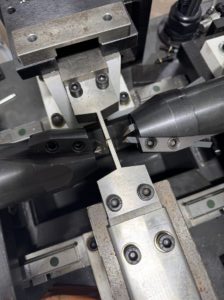
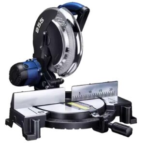
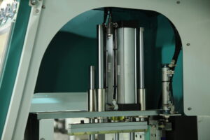
1. Enhancing Processing Efficiency and Precision
Automatic aluminum cutting machines, with their advanced control systems and precision mechanical structures, can achieve high-precision and high-efficiency cutting operations. This not only significantly improves production efficiency but also reduces labor costs, meeting the market’s demand for high-quality aluminum profiles.
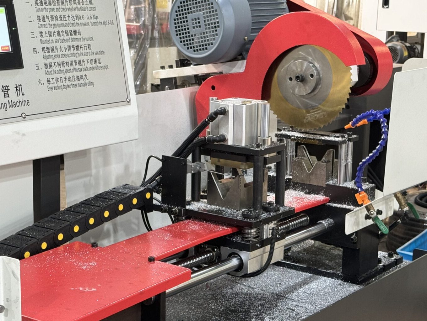
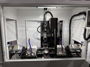
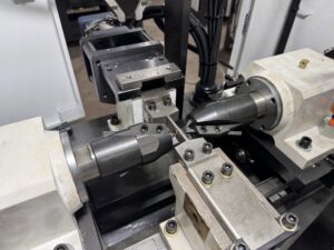
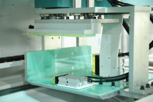
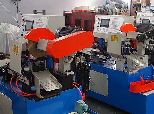
2. Intelligence and Automation
Modern automatic aluminum cutting machines are evolving towards intelligence and automation. By incorporating advanced control systems and sensor technologies, these machines can achieve remote monitoring, fault warning, and data analysis functions.
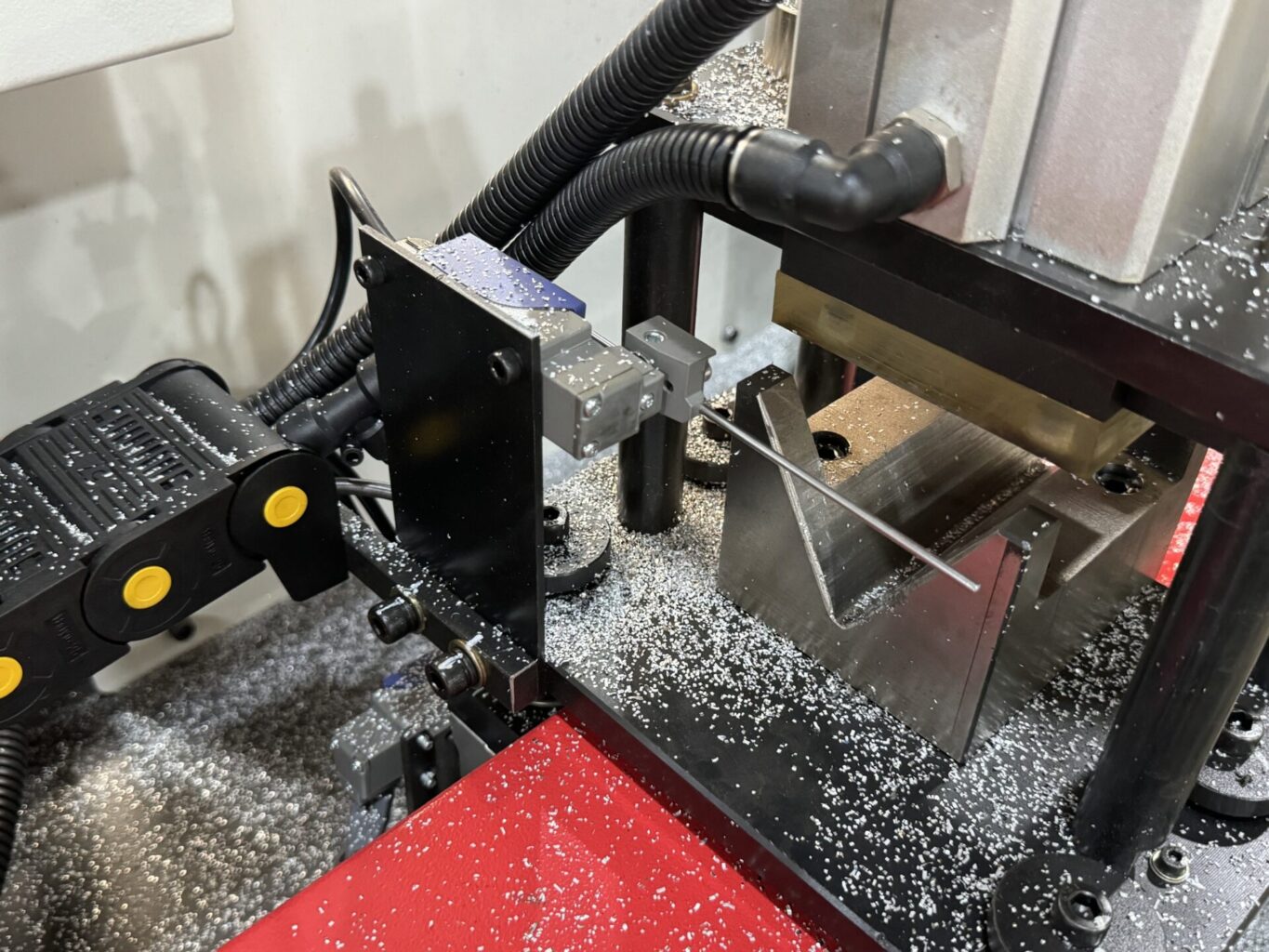
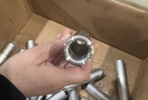
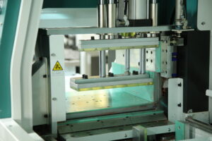
3. Meeting High-End Market Demands
In high-end fields such as aerospace and new energy vehicles, where the processing precision and efficiency requirements for aluminum profiles are extremely high, automatic aluminum cutting machines can easily handle complex aluminum part cutting tasks, providing reliable processing solutions for the high-end market.
Conclusion
The aluminum profile industry is in a period of rapid development with broad application prospects in construction, transportation, and industry. Automatic aluminum cutting machines, as key equipment for processing aluminum profiles, are providing strong support for industry development through technological innovation and intelligent upgrades. In the future, with continuous technological advancements and growing market demands, the aluminum profile industry will face even more development opportunities.